


Views: 222 Author: Bohui Electric Publish Time: 2026-07-18 Origin: Site


Content Menu
● Understanding the Enclosure, the Environment, and the Load
● Planning the Wiring Layout Before Installation
● Choosing Conductors, Terminals, and Accessories
● Installing and Bonding Protective Conductors
● Mounting Devices and Terminal Blocks
● Routing Power Circuits Inside the Enclosure
● Wiring Control, I/O, and Communication Circuits
● Termination Quality: Ferrules, Lugs, and Torque
● Organizing, Supporting, and Labeling Wiring
● Testing and Inspection Before Energizing
● Practical Insights From Industrial Projects
>> 1. How should I separate power and control cables inside an enclosure?
>> 2. What is the best way to label wires and terminals?
>> 3. How can I minimize noise affecting signal wiring?
>> 4. Why is cable bend radius important in an enclosure?
>> 5. What tests should I perform before energizing the enclosure?
Wiring an electrical enclosure is where design turns into reality. When you open the door of a finished panel and see clean routing, clear labeling, and robust terminations, you're not just looking at good craftsmanship—you're seeing a foundation for long‑term safety, reliability, and easy maintenance. In projects across power distribution, communication networks, industrial automation, building systems, energy storage, electric vehicles, and pump control, the same principles keep showing up: understand the environment, plan the layout, respect the wiring standards, and never rush the final inspection.
From a practical, hands‑on perspective, wiring an enclosure is less about "connecting wires" and more about guiding energy and information through a controlled, predictable path. That path must protect people and equipment, withstand environmental stress, and remain understandable years later when someone else opens the door to diagnose a fault or expand the system. This guide walks through proven steps and insights to help you wire an electrical enclosure with professional confidence, whether you're building a motor control center, a network cabinet, a pump controller, or an energy storage panel.
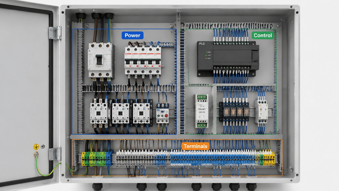
Before touching a single conductor, you need to be clear about what the enclosure will protect and where it will operate. Different applications impose different demands on wiring: a pump controller in a humid plant, a communication cabinet in a data center, a battery storage system exposed to temperature variations, or a smart manufacturing cell with mixed power and signal circuits. Each situation has unique risks and constraints.
Start by documenting the application in straightforward terms. Define voltage levels and current ranges for all circuits, including main power, auxiliary supplies, control loops, and communication lines. Note whether the enclosure will be installed indoors or outdoors, its exposure to dust, moisture, corrosive atmospheres, vibration, and expected ambient temperature. Align this with enclosure ratings and protective features, such as ingress protection levels and mechanical robustness, so the internal wiring structure supports the external conditions instead of working against them.
Experienced panel builders almost never begin wiring without a clear layout. Good planning turns a complex set of devices, terminals, and cables into a logical, easy‑to‑navigate system. A thoughtful layout also reduces rework, shortens installation time, and makes future modifications far less disruptive.
Start by reviewing single‑line diagrams, detailed schematics, and terminal assignment tables. Make sure you understand how protective conductors, power feeders, control circuits, and communication lines are supposed to flow through the enclosure. Then sketch the physical layout: incoming power near the top or side, main protection devices grouped together, distribution and control devices ordered from left to right, and terminal blocks arranged in functional groups. This mental map will guide how you route cables and where you reserve space for separation between different circuit types.
The reliability of an enclosure depends just as much on the choice of conductors and accessories as it does on the devices themselves. When wire types, lugs, terminals, and cable management hardware are correctly matched to the application, the system remains stable under electrical load and mechanical stress.
Select conductor cross‑sections to handle the expected current with appropriate margins, considering the length of runs and allowable voltage drop. Choose insulation ratings that meet or exceed the highest voltage present in the enclosure, and use shielded or twisted‑pair cable for sensitive signals and communication channels. Color coding and conductor marking should follow a consistent pattern so the function of each wire can be recognized at a glance. Matching terminals to conductor type—solid or stranded, ferruled or bare—prevents loosening, overheating, and intermittent contact issues that can be difficult to diagnose later.
Protective bonding is one of the first and most important tasks when wiring an enclosure. Good bonding practices reduce the risk that exposed metal could reach dangerous potential during fault conditions, and they stabilize reference potentials for sensitive electronic equipment.
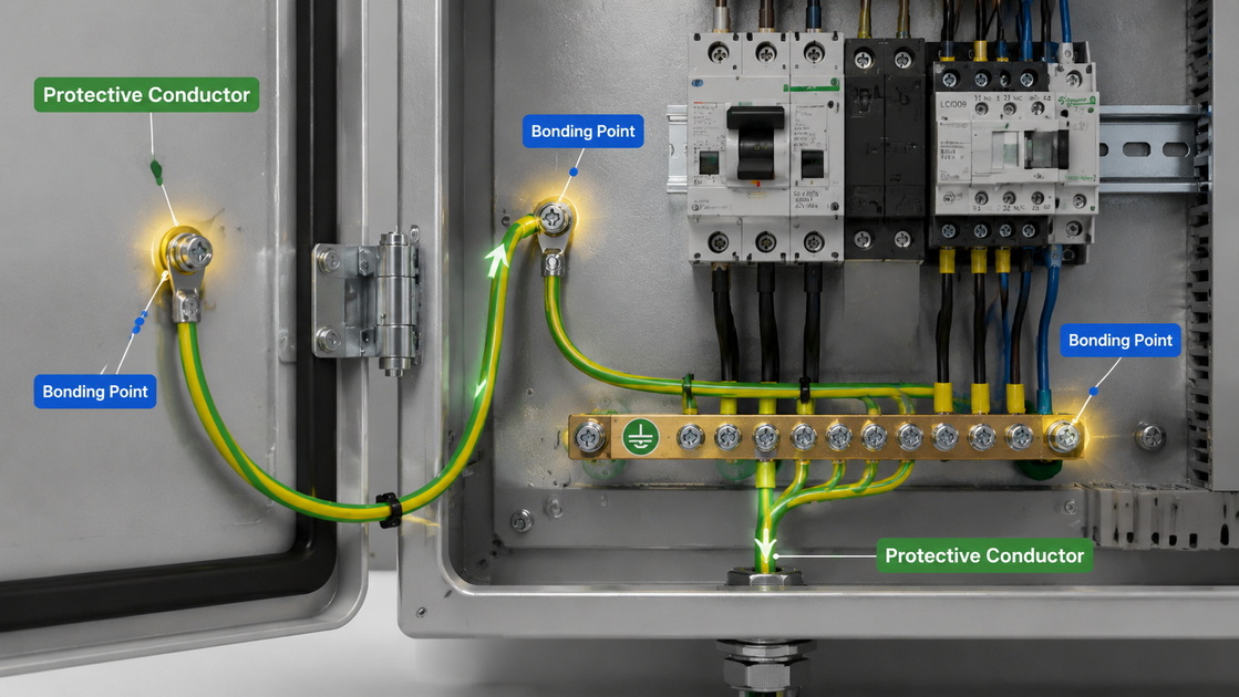
Route protective conductors early in the process, using a distinct and easily recognized color scheme. Connect enclosure doors, mounting plates, and any large metallic structures to the protective bar or grounding point using conductors sized to handle fault currents. Make sure these connections are short, direct, and mechanically secure, with appropriate hardware designed specifically for bonding. Establishing this protective network before routing power and control cables prevents improvised bonding paths and ensures every metal surface is properly referenced.
Once the protective conductors are in place, the next step is to install active devices and terminal blocks. A clear and consistent mounting strategy improves airflow, simplifies wiring routes, and reduces the risk of accidental contact during installation and maintenance.
Mount main protection and switching devices—such as circuit breakers, contactors, disconnect switches, and overload relays—in logical groups, often aligned near incoming power and distribution points. Place control devices, including relays, PLCs, power supplies, and I/O modules, in areas where they can be easily accessed for configuration or replacement. Install terminal blocks in organized rows, grouping them by function: power distribution, control outputs, signal inputs, safety circuits, and communication lines. Maintain spacing for cooling and access, and keep pathways open for cable ducts and harnesses that will connect devices and terminals together.
Routing power circuits is where planning and physical execution meet. The way you guide power cables through the enclosure has direct consequences for heat management, fault risk, and ease of troubleshooting. A disciplined approach reduces clutter and keeps high‑energy conductors away from sensitive components.
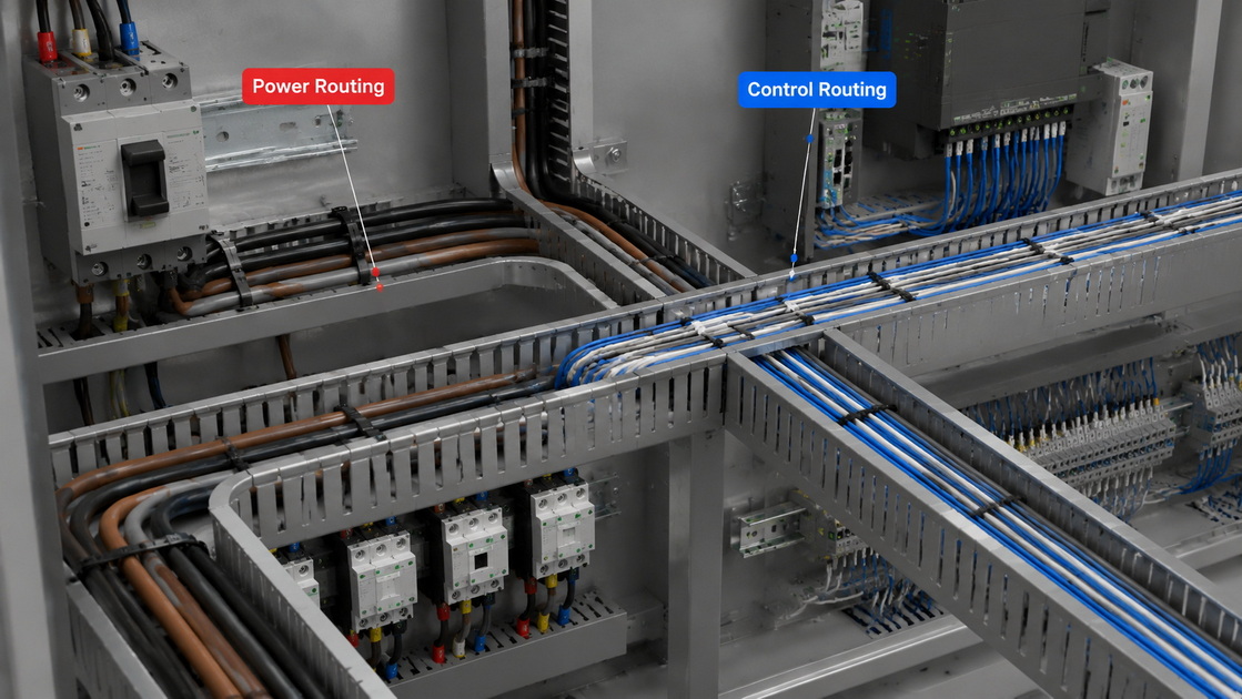
Bring incoming power cables into the enclosure through designated entries and glands, respecting bend radius requirements to preserve cable integrity. Route these conductors through dedicated ducts or trays to the main protection devices, avoiding unnecessary loops or crossing paths. From there, distribute power to downstream devices via clearly defined paths, ensuring conductors are properly supported and not resting on sharp edges. Keep high‑current cables away from control and signal wiring wherever possible, reserving space for separation and minimizing potential interference.
Control and communication wiring often carries lower voltages and currents, but it is highly sensitive to noise, improper routing, and poor shielding. Careful handling of these circuits can make the difference between a stable system and one that suffers from intermittent faults and misread signals.
Route control and communication cables in separate ducts from power wiring, and keep them grouped by function: discrete I/O, analog signals, network lines, and special‑purpose communication channels. Use shielded cables where needed, and connect shields in a consistent way according to the equipment manufacturer's recommendations. Maintain physical separation between different signal types as much as space permits, and when control or communication conductors must cross power cables, do so at right angles to minimize coupling. This attention to detail is particularly important in applications such as motor control centers, pump panels, energy storage management systems, and industrial robotics, where mixed signals co‑exist in a compact space.
High‑quality terminations are a defining characteristic of a professionally wired enclosure. The interface between conductor and terminal must remain stable, mechanically secure, and electrically sound throughout the life of the system, including periods of vibration, thermal cycling, and maintenance interventions.
Use appropriate ferrules or end sleeves for stranded conductors, especially when connecting to screw terminals or spring clamps. Choose lugs that match both conductor size and terminal type, and avoid forcing conductors into undersized connectors. Tighten each termination according to the recommended torque, not by feel alone, to prevent loosening or damage. Keep terminations clean, avoid stray strands, and never over‑fill terminals with multiple conductors unless the components are explicitly designed for that configuration. These habits significantly reduce hot spots, arcing, and intermittent faults in real‑world operation.
Once all conductors are in place, the enclosure may be electrically complete yet visually confusing. A final organization step transforms a tangle of wires into a clear, navigable system that invites confident maintenance and safe troubleshooting.

Bundle wires along designated paths using ties or clips, but avoid overtightening bundles to allow for minor repositioning and thermal expansion. Arrange cables so they follow cable ducts and channels rather than crossing freely in open air. Reserve space for future additions by keeping some pathways partially loaded instead of fully packed. Label terminal strips, device connections, and conductor ends with consistent codes that match the documentation. When a technician opens the enclosure years later, they should be able to follow each function from the schematic to the actual wire within minutes.
Before energizing the enclosure, testing and inspection confirm that the system behaves as intended and that potentially dangerous faults are caught early. This stage validates the entire wiring process and gives confidence to everyone responsible for the installation.
Start with basic checks: verify that all terminations are tight, that no insulation is damaged or pinched, and that no bare conductor is exposed where it should be covered. Perform continuity tests on protective conductors and critical control circuits to confirm that paths are complete. Measure insulation resistance where required, especially in high‑voltage or harsh environments. Finally, carry out functional tests of control sequences, interlocks, and communication channels using simulated or real field conditions. This comprehensive testing routine builds trust that the enclosure is ready for integration into larger systems and daily operation.
Across many projects in power, communication, industrial automation, building systems, pump solutions, and advanced energy applications, certain practical insights repeatedly prove their value. These lessons often come from troubleshooting faults and learning how to prevent them in future designs.
First, think about maintenance from the earliest stages. Place devices and terminal strips that are likely to require adjustment or replacement where they can be reached without removing multiple layers of equipment. Keep documentation up to date and stored close to the enclosure so teams can cross‑check reality against diagrams. Second, pay attention to inductive loads such as motors, solenoids, and large contactors. Include appropriate suppression components, such as RC networks or surge protection devices, in your wiring scheme to reduce transient stress on contacts and electronics. Third, respect temperature and environment limits. Provide clearance for ventilation, consider heat sources inside the enclosure, and route wiring so it doesn't obstruct airflow or rest directly on components that run hot.
Wiring an electrical enclosure is a disciplined craft that blends electrical knowledge, mechanical awareness, and long‑term thinking. Each decision—from conductor selection and routing paths to termination style and testing methods—affects how the enclosure will perform in daily operation across demanding environments. When wiring follows a clear plan, respects established standards, and remains organized and well documented, the enclosure becomes a stable, maintainable core of the wider system.
For teams responsible for power distribution, communication networks, industrial automation, building controls, pumps, energy storage, and related fields, refining enclosure wiring practices can have an outsized impact on uptime, safety, and lifecycle cost. By consistently applying the principles described here and adapting them to specific project requirements, you can move from reactive troubleshooting to proactive reliability, turning each enclosure into a quietly dependable part of your larger infrastructure.
Keep power cables and control or communication cables in separate ducts or trays wherever possible. Maintain physical spacing between them, and only cross paths at right angles when separation is unavoidable. This reduces electromagnetic interference and helps keep sensitive signals stable.
Use a clear, consistent labeling scheme that matches your diagrams and project documentation. Apply labels at both ends of each conductor and on terminal strips. Durable, legible labels enable technicians to quickly understand functions, trace circuits, and perform maintenance safely and efficiently.
Maintain distance between signal and power wiring, use shielded twisted‑pair cables for sensitive analog and communication lines, and connect shields according to equipment recommendations. Avoid routing signal cables parallel next to high‑current conductors for long distances, and pay attention to grounding methods for shields and reference points.
Respecting bend radius limits helps preserve the mechanical integrity of both the conductor and its insulation. Tight bends can lead to cracked insulation, internal damage, and increased stress under thermal cycling. Following recommended bend radius values extends cable life and reduces the risk of hidden faults.
Perform continuity checks on protective and key control circuits, insulation resistance tests where applicable, and functional tests that verify control logic, interlocks, and communication behavior under realistic conditions. Combine these tests with a thorough visual inspection to confirm that terminations, routing, and labeling all match the intended design.
1. Simcona. "8 Control Panel Wiring Guidelines for Industrial Electronics." https://simcona.com/blog/control-panel-wiring
2. UK Standards. "Wiring Electrical Components and Equipment in Enclosures." https://www.ukstandards.org.uk/en/nos-finder/SEMEEE332/wiring-electrical-components-and-equipment-in-enclosures
3. GT Engineering. "EN IEC 60204‑1 – Safety of Machinery: Electrical Equipment of Machines – Wiring Practices." https://www.gt-engineering.it/en/technical-standards/en-iec-standards/en-iec-60204-1-safety-of-machinery-electrical-equipment-of-machines/
4. Electric Neutron. "Standard Wiring Practices – Electrical Engineering Center." https://www.electricneutron.com/standard-wiring-practices/
5. Rockwell Automation. "Industrial Automation Wiring and Grounding Guidelines." https://literature.rockwellautomation.com/idc/groups/literature/documents/in/1770-in041_-en-p.pdf
6. Schneider Electric. "Wiring Best Practices." https://product-help.schneider-electric.com/Machine%20Expert/V2.1/en/tm3bchw/tm3bchw/D-SE-0026685.html
7. AutomationDirect Library. "Avoid Wiring Errors." https://library.automationdirect.com/avoid-wiring-errors/
8. NFPA. "General Requirements for Wiring Methods in the NEC – Article 300." https://www.nfpa.org/news-blogs-and-articles/blogs/2025/02/03/overview-of-nec-article-300

2026-07-26

2026-07-24


